Sunday, July 29, 2018

TOLERANSI DAN SUAIAN


 Toleransi (tolerance)

Toleransi ukuran (dimensional tolerance) adalah perbedaan antara dua harga batas dimana ukuran atau jarak permukaan / batas geometri suatu komponen harus terletak.
Kedua harga batas toleransi dapat dinyatakan sebagai penyimpangan (deviation) terhadap ukuran dasar yang sudah didefinisikan terlebih dahulu. Sedapat mungkin ukuran dasar dinyatakan dalam bilangan bulat. 
Toleransi

 Suaian (fit)


 Apabila dua buah komponen akan dirakit (assy), hubungan yang terjadi, yang ditimbulkan oleh karena adanya perbedaan ukuran bagi pasangan elemen geometrik sebelum mereka disatukan disebut suaian (fit).

Jenis Suaian

1.Suaian Longgar (Clearance Fit), yaitu suaian yang selalu akan menghasilkan kelonggaran (clearance) "Daerah toleransi lubang selalu terletak di atas daerah toleransi poros".
2.Suaian Pas (Transition Fit), adalah suaian yang dapat menghasilkan kelonggaran ataupun kerapatan. "Daerah toleransi lubang dan daerah toleransi poros saling berpotongan (sebagian saling menutupi)".
3.Suaian Paksa (Interference Fit), yakni suaian yang selalu akan menghasilkan kerapatan. (interference). "Daerah toleransi lubang selalu terletak di bawah daerah toleransi poros".


Sistem Suaian

Penulisan Toleransi Ukuran/Dimensi


Simbol ISO untuk Toleransi, Penyimpangan dan Suaian

Posisi daerah toleransi terhadap garis nol ditetapkan sebagai suatu fungsi ukuran dasar (berubah mengikuti perubahan ukuran dasar).  Dinyatakan dengan simbol satu huruf.
Toleransi, harganya/besarnya ditetapkan sebagai fungsi ukuran dasar. Dinyatakan dengan simbol angka (angka kualitas). 
 
Contoh :
45g6 : artinya suatu poros dengan ukuran dasar 45mm, posisi daerah toleransi mengikuti aturan kode huruf g serta besar harga toleransinya mengikuti aturan kode angka 6
65H7 : artinya suatu lubang dengan ukuran dasar 65mm, posisi daerah toleransi mengikuti aturan kode huruf H serta besar harga toleransinya mengikuti aturan kode angka 7

Sistem Suaian


Faktor-faktor untuk memilih basis suaian


  1. Macam / jenis pekerjaan
  2. Ongkos pengerjaan komponen-komponen yang harus dibuat
  3. Harga komponen-komponen yang dapat dibeli di pasaran/ dipesan dari pabrik lain
  4. Biaya pembelian perkakas potong dan alat ukur
  5. Kemudahan dari segi perancangan, pembuatan dan perakitan
Toleransi Umum (SN 258440)

Toleransi unum biasanya dibagi menjadi menjadi tiga menurut tingkat ketelitian. Yaitu halus, menengah dan kasar.

Toleransi ISO

Merupakan jenis toleransi menurut standard internasional.

Tuesday, July 24, 2018

DESIGN KALKULASI RODA GIGI LURUS (SPUR GEAR)


 Spur Gears are the simplest type of gear. The calculations for spur gears are also simple and they are used as the basisfor the calculations for other types of gears. This section introduces calculation methods of standard spur gears, profileshifted spur gears, and linear racks. The standard spur gear is a non-profile-shifted spur gear.
(1) Standard Spur Gear
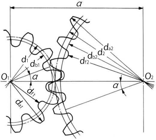
Figure 4.1 shows the meshing of standard spur gears. The meshing of standard spur gears means the reference circlesof two gears contact and roll with each other. The calculation formulas are in Table 4.1.
Fig. 4.1 The Meshing of Standard Spur Gears
( α=20°, z1=12, z2=24, x1=x2=0 )
Table 4.1 Calculations for Standard Spur Gears
No.ItemSymbolFormulaExample
Pinion (1)Gear (2)
1ModulemSet Value3
2Reference Pressure Angleα20 deg
3Number of Teethz1224
4Center DistanceaTable 4.1 Calculations for Standard Spur Gears 4NOTE154.000
5Reference Diameterdzm36.00072.000
6Base Diameterdbd cos α33.82967.658
7Addendumha1.00m3.0003.000
8Tooth Depthh2.25m6.7506.750
9Tip Diameterdad + 2m42.00078.000
10Root Diameterdfd – 2.5m28.50064.500
NOTE 1 : The subscripts 1 and 2 of z1 and z2 denote pinion and gear
All calculated values in Table 4.1 are based upon given module m and number of teeth (z1 and z2). If instead, the modulem, center distance a and speed ratio i are given, then the number of teeth, z1 and z2, would be calculated using theformulas as shown in Table 4.2.
Table 4.2 The Calculations for Number of Teeth
No.ItemSymbolFormulaExample
Pinion (1)Gear (2)
1ModulemSet Value3
2Center Distancea54.000
3Speed Ratioi1.25
4Sum of No. of Teethz1 + z2Table 4.2 The Calculations for Number of Teeth 436
5Number of TeethzTable 4.2 The Calculations for Number of Teeth 5 1Table 4.2 The Calculations for Number of Teeth5 21620

Note, that the number of teeth will probably not be integer values when using the formulas in Table 4.2. In this case,it will be necessary to resort to profile shifting or to employ helical gears to obtain as near a transmission ratioas possible.
(2) Profile Shifted Spur Gear
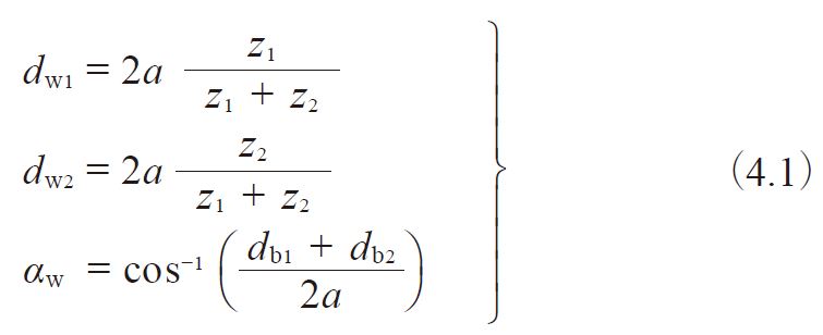
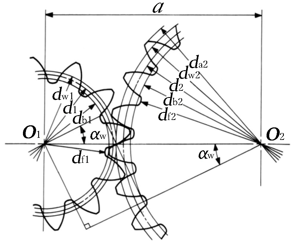
Figure 4.2 shows the meshing of a pair of profile shifted gears. The key items in profile shifted gears are the operating(working) pitch diameters (dw) and the working (operating) pressure angle (αw). These values are obtainable from themodified center distance and the following formulas :
formula 4.1
Fig. 4.2 The Meshing of Profile Shifted Gears
( α=20°, z1=12, z2=24, x1=+0.6, x2=+0.36 )
In the meshing of profile shifted gears, it is the operating pitch circle that is in contact and roll on each other thatportrays gear action. Table 4.3 presents the calculations where the profile shift coefficient has been set at x1 andx2 at the beginning. This calculation is based on the idea that the amount of the tip and root clearance should be 0.25m.
Table 4.3 The Calculations for Profile Shifted Spur Gears (1)
No.ItemSymbolFormulaExample
Pinion (1)Gear (2)
1ModulemSet Value3
2Reference Pressure Angleα20 deg
3Number of Teethz1224
4Profile Shift CoefficientX0.60.36
5Involute αwinv αwTable 4.3 The Calculations for Profile Shifted Spur Gears (1) 50.034316
6Working Pressure AngleαwFind from Involute Function Table26.0886 deg
7Center Distance
Modification Coefficient
yTable 4.3 The Calculations for Profile Shifted Spur Gears (1) 70.83329
8Center DistanceaTable 4.3 The Calculations for Profile Shifted Spur Gears (1) 856.4999
9Reference Diameterdzm36.00072.000
10Base Diameterdbd cos α33.828967.6579
11Working Pitch Diameterdw3 1137.66775.333
12Addendumha1
ha2
( 1 + y – x2 ) m
( 1 + y – x1 ) m
4.4203.700
13Tooth Depthh{2.25 + y – ( x1 + x2 )}m6.370
14Tip Diameterdad + 2ha44.84079.400
15Root Diameterdfda – 2h32.10066.660

A standard spur gear is, according to Table 4.3, a profile shifted gear with 0 coefficient of shift; that is , x1=x2=0.
Table 4.4 is the inverse formula of items from 4 to 8 of Table 4.3.
Table 4.4 The Calculations for Profile Shifted Spur Gears (2)
No.ItemSymbolFormulaExample
Pinion (1)Gear (2)
1Center DistanceaSet Value56.4999
2Center Distance
Modification Coefficient
yTable 4.4 The Calculations for Profile Shifted Spur Gears (2) 20.8333
3Working Pressure AngleαwTable 4.4 The Calculations for Profile Shifted Spur Gears (2) 326.0886 deg
4Sum of Profile Shift
Coefficient
x1 + x2Table 4.4 The Calculations for Profile Shifted Spur Gears (2) 40.9600
5Profile Shift Coefficientx0.60000.3600

There are several theories concerning how to distribute the sum of profile shift coefficient (x1 + x2) into pinion (x1)and gear (x2) separately. BSS (British) and DIN (German) standards are the most often used. In the example above, the12 tooth pinion was given sufficient correction to preventundercut, and the residual profile shift was given to the mating gear.
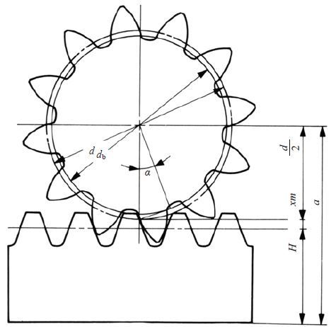
(3) Rack and Spur Gear
Table 4.5 presents the method for calculating the mesh of a rack and spur gear.
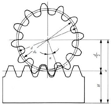
Figure 4.3 (1) shows the the meshing of standard gear and a rack. In this mesh, the reference circle of the gear touchesthe pitch line of the rack.
Figure 4.3 (2) shows a profile shifted spur gear, with positive correction xm, meshed with a rack. The spur gear hasa larger pitch radius than standard, by the amount xm. Also, the pitch line of the rack has shifted outward by the amountxm.
Table 4.5 presents the calculation of a meshed profile shifted spur gear and rack. If the profile shift coefficientx1 is 0, then it is the case of a standard gear meshed with the rack.
Table 4.5 The calculations of dimensions of a profile shifted spur gear and a rack
No.ItemSymbolFormulaExample
Spur gearRack
1ModulemSet Value3
2Reference pressure anglea20 deg
3Number of teethz12
4Profile shift coefficientx0.6
5Height of pitch lineH32.000
6Working pressure angleαw20 deg
7Mounting distanceaTable 4.5 The calculations of dimensions of a profile shifted spur gear and a rack 751.800
8Reference diameterdzm36.000
9Base diameterdbd cos α33.829
10Working pitch diameterdw5 1036.000
11Addendumham ( 1 + x )4.8003.000
12Tooth depthh2.25m6.750
13Tip diameterdad + 2ha45.600
14Root diameterdfda – 2h32.100

One rotation of the spur gear will displace the rack l one circumferential length of the gear’s reference circle,per the formula :
formula 4.2
The rack displacement, l, is not changed in any way by the profile shifting. Equation (4.2) remains applicable for anyamount of profile shift.
Fig. 4.3 (1) The meshing of standard spur gear and rack
( α=20°, z1=12, x1=0 )
Fig. 4.3 (2) The meshing of profile shifted spur gear and rack
( α=20°, z1=12, x1=+ 0.6 )
 
Rumus yang dipakai : 
No       Simbol        Keterangan                Rumus 
1.             M               Modul                     M = Dp/Z 
                                                                  M = Dk/(Z+2) 
2              Z             Jumlah gigi                Z  = Dp/M 
3             Dk         Diameter kepala           Dk = (Z+2).M 
4             Dp         Diameter pitch             Dp = Z.M 
5             Df          Diameter kaki              Df = Dp+(2.M) 
                                                                  Df = (Z-2,5)M 
6             Hk         Tinggi kepala kaki      1.M 
7             Hf          Tinggi kaki gigi          1,16.M 
8             H           Tinggi kaki                  2,16.M 
9             B            Lebar gigi                   10.M