Spur Gears are the simplest type of gear. The calculations for spur
gears are also simple and they are used as the basisfor the calculations
for other types of gears. This section introduces calculation methods
of standard spur gears, profileshifted spur gears, and linear racks. The
standard spur gear is a non-profile-shifted spur gear.
(1) Standard Spur Gear
Figure 4.1 shows the meshing of standard spur gears. The meshing of standard spur gears means the reference circlesof two gears contact and roll with each other. The calculation formulas are in Table 4.1.
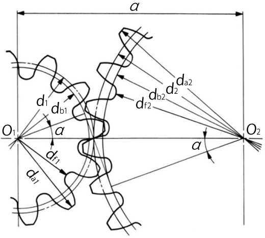
Fig. 4.1 The Meshing of Standard Spur Gears
( α=20°, z1=12, z2=24, x1=x2=0 )
Table 4.1 Calculations for Standard Spur Gears
NOTE 1 : The subscripts 1 and 2 of z1 and z2 denote pinion and gear
All calculated values in Table 4.1 are based upon given module m and number of teeth (z1 and z2). If instead, the modulem, center distance a and speed ratio i are given, then the number of teeth, z1 and z2, would be calculated using theformulas as shown in Table 4.2.
Table 4.2 The Calculations for Number of Teeth
Note, that the number of teeth will probably not be integer values when using the formulas in Table 4.2. In this case,it will be necessary to resort to profile shifting or to employ helical gears to obtain as near a transmission ratioas possible.
(2) Profile Shifted Spur Gear
Figure 4.2 shows the meshing of a pair of profile shifted gears. The key items in profile shifted gears are the operating(working) pitch diameters (dw) and the working (operating) pressure angle (αw). These values are obtainable from themodified center distance and the following formulas :
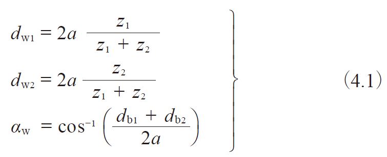
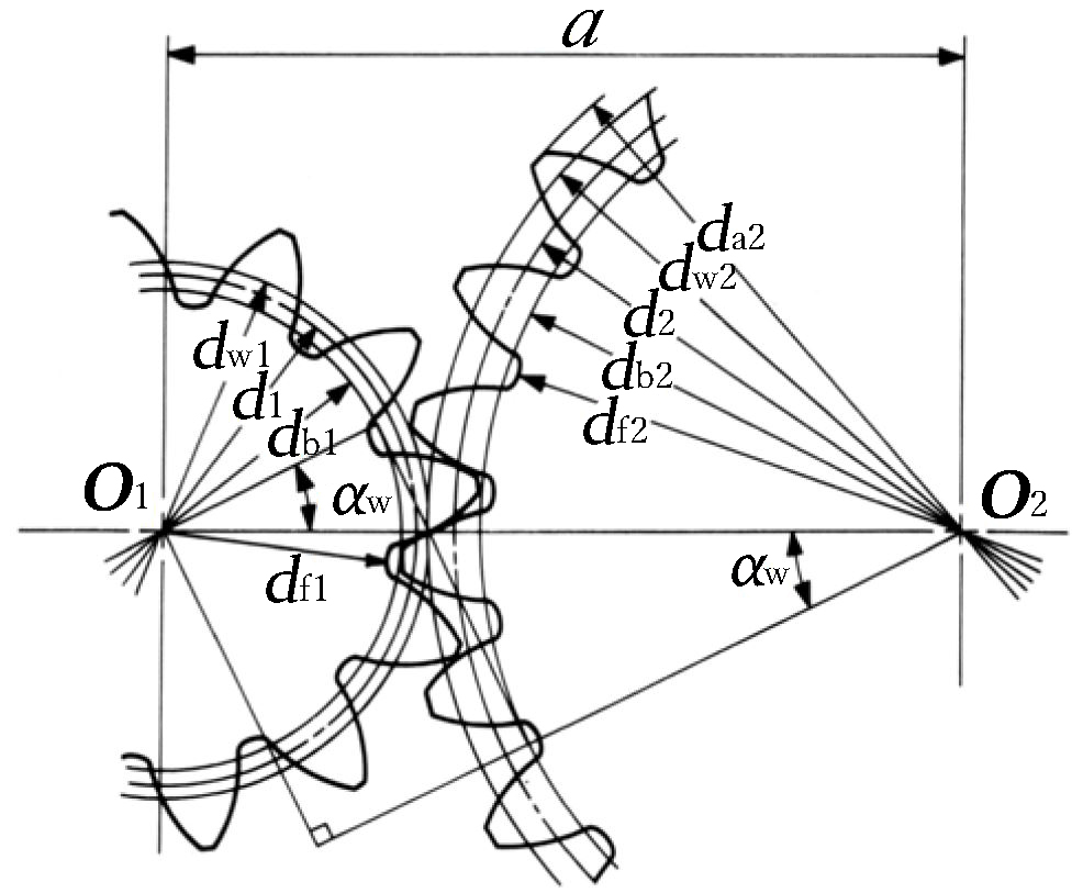
Fig. 4.2 The Meshing of Profile Shifted Gears
( α=20°, z1=12, z2=24, x1=+0.6, x2=+0.36 )
In the meshing of profile shifted gears, it is the operating pitch circle that is in contact and roll on each other thatportrays gear action. Table 4.3 presents the calculations where the profile shift coefficient has been set at x1 andx2 at the beginning. This calculation is based on the idea that the amount of the tip and root clearance should be 0.25m.
Table 4.3 The Calculations for Profile Shifted Spur Gears (1)
A standard spur gear is, according to Table 4.3, a profile shifted gear with 0 coefficient of shift; that is , x1=x2=0.
Table 4.4 is the inverse formula of items from 4 to 8 of Table 4.3.
Table 4.4 The Calculations for Profile Shifted Spur Gears (2)
There are several theories concerning how to distribute the sum of profile shift coefficient (x1 + x2) into pinion (x1)and gear (x2) separately. BSS (British) and DIN (German) standards are the most often used. In the example above, the12 tooth pinion was given sufficient correction to preventundercut, and the residual profile shift was given to the mating gear.
(3) Rack and Spur Gear
Table 4.5 presents the method for calculating the mesh of a rack and spur gear.
Figure 4.3 (1) shows the the meshing of standard gear and a rack. In this mesh, the reference circle of the gear touchesthe pitch line of the rack.
Figure 4.3 (2) shows a profile shifted spur gear, with positive correction xm, meshed with a rack. The spur gear hasa larger pitch radius than standard, by the amount xm. Also, the pitch line of the rack has shifted outward by the amountxm.
Table 4.5 presents the calculation of a meshed profile shifted spur gear and rack. If the profile shift coefficientx1 is 0, then it is the case of a standard gear meshed with the rack.
Table 4.5 The calculations of dimensions of a profile shifted spur gear and a rack
One rotation of the spur gear will displace the rack l one circumferential length of the gear’s reference circle,per the formula :

The rack displacement, l, is not changed in any way by the profile shifting. Equation (4.2) remains applicable for anyamount of profile shift.
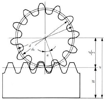
Fig. 4.3 (1) The meshing of standard spur gear and rack
( α=20°, z1=12, x1=0 )
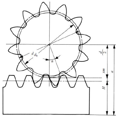
Fig. 4.3 (2) The meshing of profile shifted spur gear and rack
( α=20°, z1=12, x1=+ 0.6 )
(1) Standard Spur Gear
Figure 4.1 shows the meshing of standard spur gears. The meshing of standard spur gears means the reference circlesof two gears contact and roll with each other. The calculation formulas are in Table 4.1.

Fig. 4.1 The Meshing of Standard Spur Gears
( α=20°, z1=12, z2=24, x1=x2=0 )
Table 4.1 Calculations for Standard Spur Gears
| No. | Item | Symbol | Formula | Example | |
| Pinion (1) | Gear (2) | ||||
| 1 | Module | m | Set Value | 3 | |
| 2 | Reference Pressure Angle | α | 20 deg | ||
| 3 | Number of Teeth | z | 12 | 24 | |
| 4 | Center Distance | a | 54.000 | ||
| 5 | Reference Diameter | d | zm | 36.000 | 72.000 |
| 6 | Base Diameter | db | d cos α | 33.829 | 67.658 |
| 7 | Addendum | ha | 1.00m | 3.000 | 3.000 |
| 8 | Tooth Depth | h | 2.25m | 6.750 | 6.750 |
| 9 | Tip Diameter | da | d + 2m | 42.000 | 78.000 |
| 10 | Root Diameter | df | d – 2.5m | 28.500 | 64.500 |
All calculated values in Table 4.1 are based upon given module m and number of teeth (z1 and z2). If instead, the modulem, center distance a and speed ratio i are given, then the number of teeth, z1 and z2, would be calculated using theformulas as shown in Table 4.2.
Table 4.2 The Calculations for Number of Teeth
| No. | Item | Symbol | Formula | Example | ||
| Pinion (1) | Gear (2) | |||||
| 1 | Module | m | Set Value | 3 | ||
| 2 | Center Distance | a | 54.000 | |||
| 3 | Speed Ratio | i | 1.25 | |||
| 4 | Sum of No. of Teeth | z1 + z2 | 36 | |||
| 5 | Number of Teeth | z | 16 | 20 | ||
Note, that the number of teeth will probably not be integer values when using the formulas in Table 4.2. In this case,it will be necessary to resort to profile shifting or to employ helical gears to obtain as near a transmission ratioas possible.
(2) Profile Shifted Spur Gear
Figure 4.2 shows the meshing of a pair of profile shifted gears. The key items in profile shifted gears are the operating(working) pitch diameters (dw) and the working (operating) pressure angle (αw). These values are obtainable from themodified center distance and the following formulas :


Fig. 4.2 The Meshing of Profile Shifted Gears
( α=20°, z1=12, z2=24, x1=+0.6, x2=+0.36 )
In the meshing of profile shifted gears, it is the operating pitch circle that is in contact and roll on each other thatportrays gear action. Table 4.3 presents the calculations where the profile shift coefficient has been set at x1 andx2 at the beginning. This calculation is based on the idea that the amount of the tip and root clearance should be 0.25m.
Table 4.3 The Calculations for Profile Shifted Spur Gears (1)
| No. | Item | Symbol | Formula | Example | |
| Pinion (1) | Gear (2) | ||||
| 1 | Module | m | Set Value | 3 | |
| 2 | Reference Pressure Angle | α | 20 deg | ||
| 3 | Number of Teeth | z | 12 | 24 | |
| 4 | Profile Shift Coefficient | X | 0.6 | 0.36 | |
| 5 | Involute αw | inv αw | 0.034316 | ||
| 6 | Working Pressure Angle | αw | Find from Involute Function Table | 26.0886 deg | |
| 7 | Center Distance Modification Coefficient | y | 0.83329 | ||
| 8 | Center Distance | a | 56.4999 | ||
| 9 | Reference Diameter | d | zm | 36.000 | 72.000 |
| 10 | Base Diameter | db | d cos α | 33.8289 | 67.6579 |
| 11 | Working Pitch Diameter | dw | 37.667 | 75.333 | |
| 12 | Addendum | ha1 ha2 | ( 1 + y – x2 ) m ( 1 + y – x1 ) m | 4.420 | 3.700 |
| 13 | Tooth Depth | h | {2.25 + y – ( x1 + x2 )}m | 6.370 | |
| 14 | Tip Diameter | da | d + 2ha | 44.840 | 79.400 |
| 15 | Root Diameter | df | da – 2h | 32.100 | 66.660 |
A standard spur gear is, according to Table 4.3, a profile shifted gear with 0 coefficient of shift; that is , x1=x2=0.
Table 4.4 is the inverse formula of items from 4 to 8 of Table 4.3.
Table 4.4 The Calculations for Profile Shifted Spur Gears (2)
| No. | Item | Symbol | Formula | Example | |
| Pinion (1) | Gear (2) | ||||
| 1 | Center Distance | a | Set Value | 56.4999 | |
| 2 | Center Distance Modification Coefficient | y | 0.8333 | ||
| 3 | Working Pressure Angle | αw |  | 26.0886 deg | |
| 4 | Sum of Profile Shift Coefficient | x1 + x2 | 0.9600 | ||
| 5 | Profile Shift Coefficient | x | – | 0.6000 | 0.3600 |
There are several theories concerning how to distribute the sum of profile shift coefficient (x1 + x2) into pinion (x1)and gear (x2) separately. BSS (British) and DIN (German) standards are the most often used. In the example above, the12 tooth pinion was given sufficient correction to preventundercut, and the residual profile shift was given to the mating gear.
(3) Rack and Spur Gear
Table 4.5 presents the method for calculating the mesh of a rack and spur gear.
Figure 4.3 (1) shows the the meshing of standard gear and a rack. In this mesh, the reference circle of the gear touchesthe pitch line of the rack.
Figure 4.3 (2) shows a profile shifted spur gear, with positive correction xm, meshed with a rack. The spur gear hasa larger pitch radius than standard, by the amount xm. Also, the pitch line of the rack has shifted outward by the amountxm.
Table 4.5 presents the calculation of a meshed profile shifted spur gear and rack. If the profile shift coefficientx1 is 0, then it is the case of a standard gear meshed with the rack.
Table 4.5 The calculations of dimensions of a profile shifted spur gear and a rack
| No. | Item | Symbol | Formula | Example | |
| Spur gear | Rack | ||||
| 1 | Module | m | Set Value | 3 | |
| 2 | Reference pressure angle | a | 20 deg | ||
| 3 | Number of teeth | z | 12 | – | |
| 4 | Profile shift coefficient | x | 0.6 | ||
| 5 | Height of pitch line | H | – | 32.000 | |
| 6 | Working pressure angle | αw | 20 deg | ||
| 7 | Mounting distance | a | 51.800 | ||
| 8 | Reference diameter | d | zm | 36.000 | – |
| 9 | Base diameter | db | d cos α | 33.829 | |
| 10 | Working pitch diameter | dw | 36.000 | ||
| 11 | Addendum | ha | m ( 1 + x ) | 4.800 | 3.000 |
| 12 | Tooth depth | h | 2.25m | 6.750 | |
| 13 | Tip diameter | da | d + 2ha | 45.600 | – |
| 14 | Root diameter | df | da – 2h | 32.100 | |
One rotation of the spur gear will displace the rack l one circumferential length of the gear’s reference circle,per the formula :
The rack displacement, l, is not changed in any way by the profile shifting. Equation (4.2) remains applicable for anyamount of profile shift.

Fig. 4.3 (1) The meshing of standard spur gear and rack
( α=20°, z1=12, x1=0 )

Fig. 4.3 (2) The meshing of profile shifted spur gear and rack
( α=20°, z1=12, x1=+ 0.6 )
Rumus yang dipakai :
No Simbol Keterangan Rumus
1. M Modul M = Dp/Z
M = Dk/(Z+2)
2 Z Jumlah gigi Z = Dp/M
3 Dk Diameter kepala Dk = (Z+2).M
4 Dp Diameter pitch Dp = Z.M
5 Df Diameter kaki Df = Dp+(2.M)
Df = (Z-2,5)M
6 Hk Tinggi kepala kaki 1.M
7 Hf Tinggi kaki gigi 1,16.M
8 H Tinggi kaki 2,16.M
9 B Lebar gigi 10.M

No comments:
Post a Comment